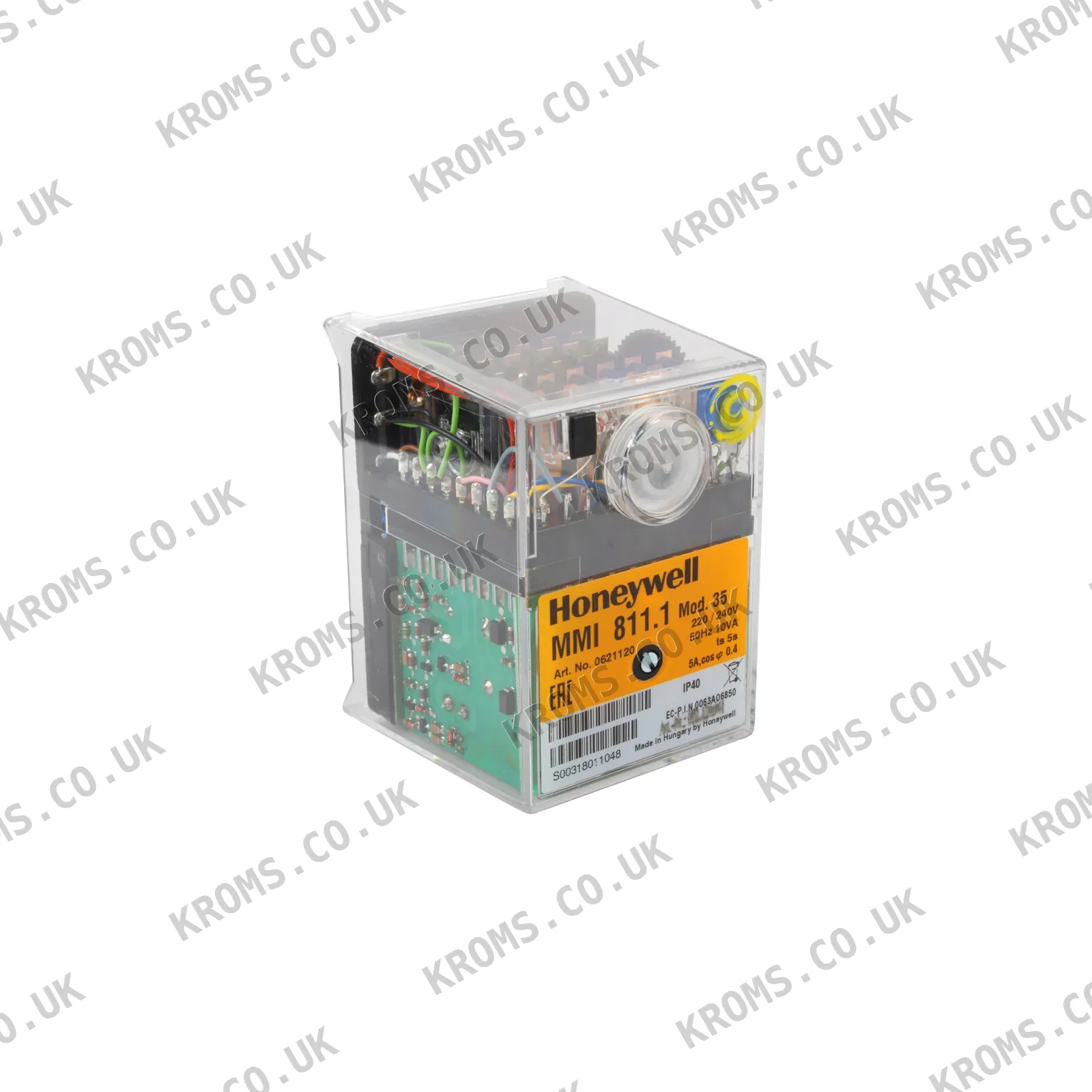
Honeywell Gas burner safety control box MMI811.1 mod.35 0621120
SKU 0621120
Model MMI811.1 mod.35
Brand Honeywell
Photos
Key specifications
| Supply voltage | 220–240 V |
|---|---|
| Safety time | 5 s |
| Flame detector type | ionization probe, infrared flicker detector |
| Protection class (IP) | IP44 |
| Body material | non-flammable plastic |
| Waiting time | 9 s |
| Air proving switch | 6.0 s |
| Time delay term.6 / term.C | 10 s |
| Power consumption | 10 W |
| Amplifier sensitivity | 1 µA |
| Min. current from UV tube or ionisation probe | 5 µA |
| Weight incl. wiring base | 350 kg |
| Fuel | gas or oil |
| Firing stages | two-stage |
| Infrared detector model | IRD 1020 |
| Pre-purge time | 24 s |
| Pre-ignition time | 3 s |
| Net weight | 0.35 kg |
461.34 EUR
419.40EUR
in stock · 1
incl. 21% VAT · 346.61 EUR excl. VAT · shipping calculated at checkout
- Worldwide shipping from stock
- Original manufacturer part
- Dispatch within 24 h for stocked items
Description
The Honeywell MMI811.1 mod.35 is a gas burner safety control box designed for two-stage forced draught and combi oil/gas burners. It operates on a supply voltage of 220–240 V and consumes 10 W. The control box features a waiting time of 9 s, a pre-purge time of 24 s, a pre-ignition time of 3 s, and a safety time of 5 s. It supports flame detection via an ionization probe or an infrared flicker detector (model IRD 1020). The device is housed in a non-flammable plastic casing with IP44 protection and weighs 0.35 kg net.
Further details
| Air pressure monitor | working contact 4 A, 230 V |
|---|---|
| Classified acc. to EN 298 | BTLLXN |
| Flame detector cable | max. 20 m cable length |
| Fuse rating | max. 10 A rapid, 6 A slow |
| Infrared flare detector | IRD 1020 |
| Insulation standard | IP 44 |
| Mounting attitude | any |
| Permissable ambient temp. | -20° C... +60°C |
Choosing and fitting
Parts of this type are selected by matching the supply voltage, flame detector type, and timing parameters to the burner's requirements. The control box must be compatible with the burner's stage configuration and the specific flame detector used. Installation involves mounting the control box in any attitude and connecting the wiring base according to the burner's electrical diagram. Ensure the air proving switch reaction time and time delay settings align with the system's specifications.
Signs of failure
Common failures include the control box not starting or locking out due to flame detection issues, such as a faulty ionization probe or infrared detector. Symptoms may include the burner failing to ignite, repeated safety lockouts, or the control box not advancing through its program sequence. Check the flame detector current, wiring connections, and the control box's internal cam mechanism for wear or damage.
All specifications
| Supply voltage | 220–240 V |
|---|---|
| Safety time | 5 s |
| Flame detector type | ionization probe, infrared flicker detector |
| Protection class (IP) | IP44 |
| Body material | non-flammable plastic |
| Waiting time | 9 s |
| Air proving switch | 6.0 s |
| Time delay term.6 / term.C | 10 s |
| Power consumption | 10 W |
| Amplifier sensitivity | 1 µA |
| Min. current from UV tube or ionisation probe | 5 µA |
| Weight incl. wiring base | 350 kg |
| Fuel | gas or oil |
| Firing stages | two-stage |
| Infrared detector model | IRD 1020 |
| Pre-purge time | 24 s |
| Pre-ignition time | 3 s |
| Net weight | 0.35 kg |
Part numbers
| SKU | 0621120 |
|---|---|
| Additional article | 852.124.041 |
| Model | MMI811.1 mod.35 |