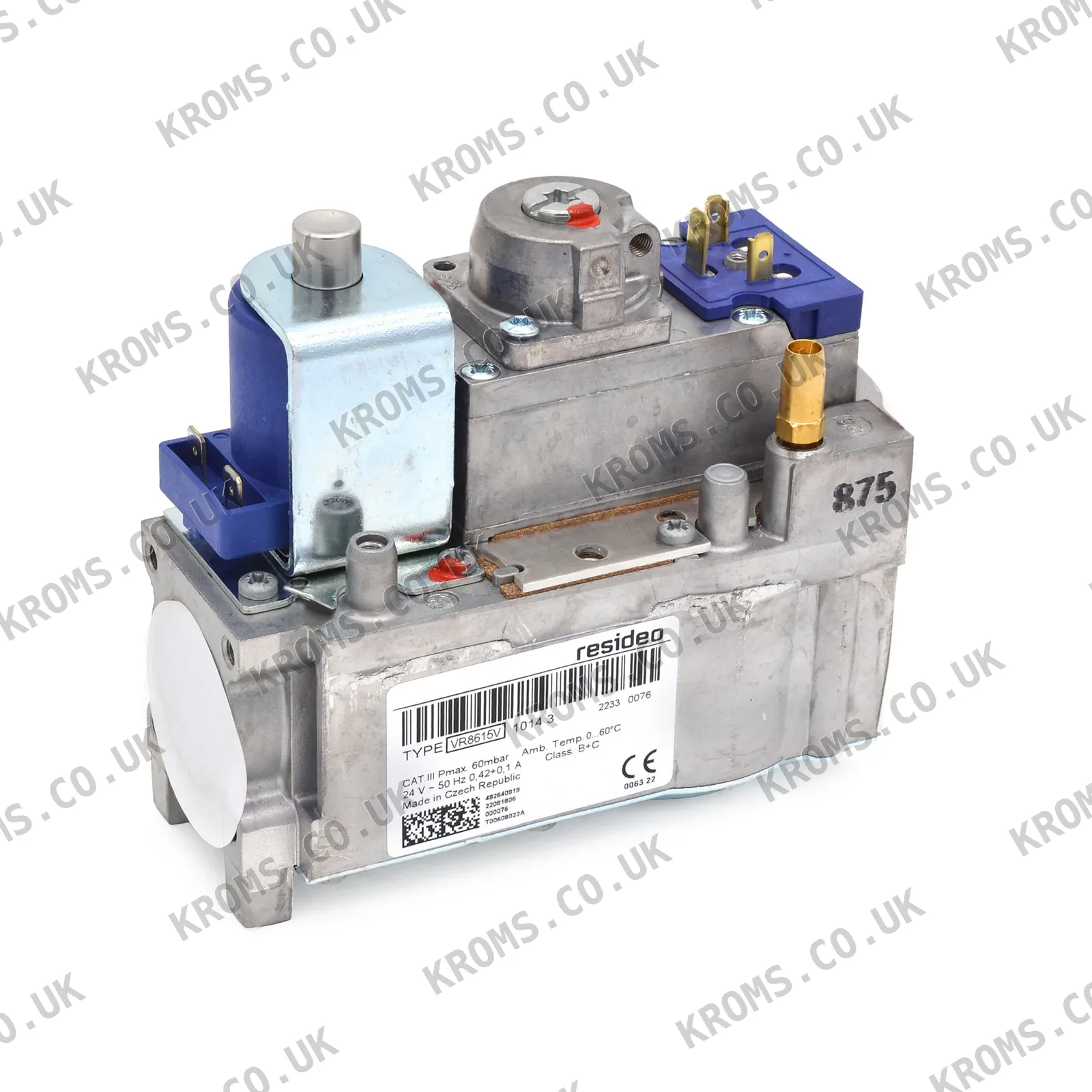
Honeywell Gas solenoid valves VR8615V1014U
SKU VR8615V1014U
Brand Honeywell
Photos
Key specifications
| Max. inlet pressure | 60 mbar |
|---|---|
| Back pressure (1st valve) | 50 mbar |
| Maximum inlet pressure | 60 mbar |
| Output aperture diameter | 2.8 mm |
| Nominal inlet gas pressure | 25 mbar |
| Ambient pressure | 1013 mbar |
| Pressure sensor pipe diameter | 0.5 inch |
| Inlet and outlet diameter | 18.6 mm |
| Maximum air pressure (before ignition) | 8 mbar |
| Maximum air pressure (after ignition) | 20 mbar |
| Operator part number | V8346A 1031 (45.801.155-006) |
| Leakage requirements | EN 126 |
| Certification standard | EN 161 |
| Solenoid configuration | two electric actuators |
| Actuator type | two-position electric actuator |
| Ignition systems supported | DSI, HSI, IP |
| Power options | mains and low-voltage |
| Flow indication | yes |
| Built-in filter | fine-mesh filter on input side |
| Optional output filter | yes |
| Electrical connection | connector according to DIN standard |
| Regulator spring lock | yes |
| Valve closing force variants | B+B, B+J, B+C, A+J, A+C |
| Design features | positive feedback system |
| Input screen | on input side |
| connection_type | flanged connection |
| Flow capacity | 7.5 m³/h |
| Certification | CE |
519.09 EUR
471.90EUR
in stock · 2
incl. 21% VAT · 390.00 EUR excl. VAT · shipping calculated at checkout
- Worldwide shipping from stock
- Original manufacturer part
- Dispatch within 24 h for stocked items
Description
The Honeywell VR8615V1014U is a gas solenoid valve designed for controlling gas flow in heating systems, boilers, and water heaters. It features two electric actuators for safety and main valve control, supporting DSI, HSI, and IP ignition systems. The valve has a maximum inlet pressure of 60 mbar, a flow capacity of 7.5 m³/h, and includes a fine-mesh filter on the input side. It operates with a nominal inlet pressure of 25 mbar and is certified to CE standards (EN 161).
Further details
| Application | gas heating systems with main burner |
|---|---|
| Control Features | two-level control and gas flow modulation |
| Gas Type | petroleum gases MFD group A (G110), MFD group B (G120), natural gas H (G20), natural gas L (G25), liquefied gas LP (G30) |
| Mounting Feature | two threaded mounting holes in the base |
| Operating Principle | automatic control of gas outlet pressure with positive feedback |
| Output Pressure Stability | stable outlet pressure regardless of inlet pressure changes |
| Pressure Measuring Points | fittings with outer diameter 9 mm on inlet and outlet |
| Safety Feature | valve closes in case of power failure or gas supply interruption |
Choosing and fitting
Parts of this type are selected by matching the inlet and outlet diameters, connection type (flanged), and electrical connection (DIN standard connector). The valve must be compatible with the ignition system (DSI, HSI, IP) and power options (mains or low-voltage). Ensure the closing variant (e.g., B+B, B+J) matches the system requirements. Installation should consider the actuator orientation, which can be positioned within a 90° angle from vertical.
Signs of failure
Common failures include valve sticking or failing to open/close, leading to no gas flow or continuous flow. Symptoms may include burner ignition failure, unstable flame, or system shutdown. Check for debris clogging the fine-mesh filter, electrical connection issues, or actuator malfunction. Verify the valve's response to power loss, as it should close automatically.
All specifications
| Max. inlet pressure | 60 mbar |
|---|---|
| Back pressure (1st valve) | 50 mbar |
| Maximum inlet pressure | 60 mbar |
| Output aperture diameter | 2.8 mm |
| Nominal inlet gas pressure | 25 mbar |
| Ambient pressure | 1013 mbar |
| Pressure sensor pipe diameter | 0.5 inch |
| Inlet and outlet diameter | 18.6 mm |
| Maximum air pressure (before ignition) | 8 mbar |
| Maximum air pressure (after ignition) | 20 mbar |
| Operator part number | V8346A 1031 (45.801.155-006) |
| Leakage requirements | EN 126 |
| Certification standard | EN 161 |
| Solenoid configuration | two electric actuators |
| Actuator type | two-position electric actuator |
| Ignition systems supported | DSI, HSI, IP |
| Power options | mains and low-voltage |
| Flow indication | yes |
| Built-in filter | fine-mesh filter on input side |
| Optional output filter | yes |
| Electrical connection | connector according to DIN standard |
| Regulator spring lock | yes |
| Valve closing force variants | B+B, B+J, B+C, A+J, A+C |
| Design features | positive feedback system |
| Input screen | on input side |
| connection_type | flanged connection |
| Flow capacity | 7.5 m³/h |
| Certification | CE |
Part numbers
| SKU | VR8615V1014U |
|---|---|
| Additional article | 534.322.219 |
| Type designation | 45.801.155-006 |