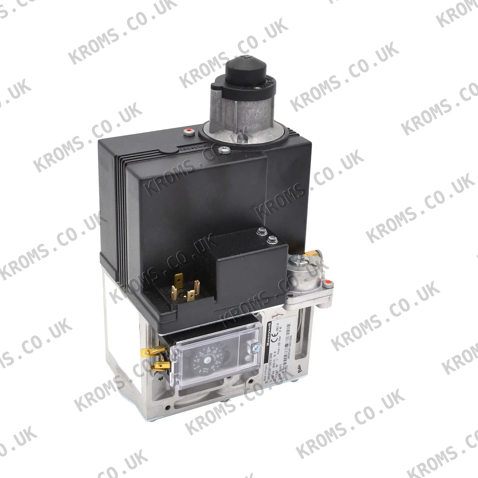
Honeywell Gas valve VR425AF1003-1000
SKU VR425AF1003-1000
Brand Honeywell
Photos
Key specifications
| Nominal diameter (DN) | 25 mm |
|---|---|
| Max. inlet pressure | 200 mbar |
| Supply voltage | 230 V |
| Maximum operating pressure | 200 mbar |
| Housing IP | ip 40 |
| Body material | aluminum alloy, injection molding |
| Filter element cell size | 0.34 mm |
| Closing spring material | aisi 302 steel |
| Valve plunger coating | fe 360 coating |
| Mesh filter standard | en 161 |
| Flange kit | 1 flange with sealing plug, 1 o-ring, 4 screws, 1 pressure measuring fitting |
| Valve V1 operation | always opens/closes quickly |
| Pressure control valve location | between valves v1 and v2 |
| Flange connections | 4 |
| Inlet pressure switch compatibility | c60vr series |
| Intermediate pressure switch compatibility | c60vr series |
| Valve inspection system compatibility | vps + pressure switch |
| Strainer material | aisi 303 steel |
| Valve class | class a + a |
| Regulator class | class c |
| Pressure measuring fittings | 1 pressure measuring fitting installed |
| Distance to wall/floor | at least 30 cm |
| Pressure regulation | adjustment screw |
| Gas type | gaseous fuel |
| Supply frequency | 50–60 Hz |
| Housing protection | ip 40 |
| Adjustment screw | used for pressure regulation |
| Clearance requirement | at least 30 cm from wall/floor |
| Electrical safety | en 60335 series |
| Frequency | 50 Hz |
| Flow capacity | 1 m³/h |
866.87 EUR
788.06EUR
in stock · 3
incl. 21% VAT · 651.29 EUR excl. VAT · shipping calculated at checkout
- Worldwide shipping from stock
- Original manufacturer part
- Dispatch within 24 h for stocked items
Description
The Honeywell VR425AF1003-1000 is a gas valve with a nominal diameter of 25 mm, designed for controlling and regulating gaseous fuel supply in high-power burners and boilers. It operates at a supply voltage of 230 V and a frequency of 50 Hz, with a maximum operating pressure of 200 mbar and a flow capacity of 1 m³/h. The valve features two main valves (V1 and V2) with V1 opening and closing quickly, and a pressure control valve located between them. It has 4 flange connections for accessories, an IP 40 housing, and is made of aluminum alloy with a mesh filter of 0.34 mm cell size. The valve is classified as Class A + A and the regulator as Class C, with a clearance requirement of at least 30 cm from walls or floors.
Further details
| Actuator Components | coil and a sleeve, where there is a plunger connected to a rubber valve and covered with an anti-friction material |
|---|---|
| Actuator description | coil and sleeve with plunger connected to rubber valve covered with anti-friction material |
| Application | high-power gas burners, atmospheric gas boilers, melting furnaces, incinerators and other gas consuming devices |
| Built In Valve | two main valves v1 and v2 |
| Design principle | controlled by devices with two positions that open and close the valves |
| Discharge behavior | when disconnected, a small volume of working gas from the regulator is discharged into the main chamber |
| EMC compliance | all standards for electromagnetic compatibility for non-industrial and industrial installations |
| Electromagnetic compatibility standard | all standards for electromagnetic compatibility for non-industrial and industrial installations |
| Ignition Systems Supported | spark ignition of the burner (dbi) and for systems with a pilot burner (ip) |
| Ignition system types | dbi (spark ignition) and ip (pilot burner) |
| Installation Position | can be installed at an angle of plus or minus 90 degrees to the vertical |
| Installation Requirement | distance between the gas valve and the wall/floor must be at least 30 cm |
| Mounting angle | plus or minus 90 degrees to vertical |
| Mounting position | can be installed at an angle of plus or minus 90 degrees to the vertical |
| Operating Principle | pressure servo controller with a pressure relief valve built into the diaphragm of the regulator controlling the control valve |
| Output pressure stability | keeps the exhaust pressure at the same level, regardless of changes in the intake pressure |
| Purpose | control and regulate the supply of gaseous fuel in high-power gas burners, atmospheric gas boilers, melting furnaces, incinerators and other gas consuming devices |
| Regulator Classification | class c according to en 126/en 88 |
| Seal Material | hydrocarbon-resistant types of butadiene-acrylonitrile (nbr) and viton rubber |
| Seal material detail | hydrocarbon-resistant butadiene-acrylonitrile (nbr) and viton rubber |
| Servo controller | pressure servo controller with pressure relief valve |
| Spring mechanism | spring pressure keeps valves in open position |
| Strainer cleaning | can be cleaned by unscrewing the inlet flange screws |
| Valve Classification | class a + a according to en 126/en 161 |
| Valve V2 function | second valve, can be operated quickly or slowly with flow control and adjustable opening |
Choosing and fitting
When selecting a gas valve of this type, ensure the nominal diameter, maximum operating pressure, supply voltage, and frequency match the system requirements. The valve must be compatible with the gas type and have appropriate flange connections for the installation of pressure switches or inspection systems. Mounting can be at an angle of ±90 degrees to vertical, but maintain a minimum distance of 30 cm from walls or floors. Verify the valve's flow capacity meets the burner's demand and that the electrical safety standards align with the equipment.
Signs of failure
Common failures include valve sticking due to debris or wear, leading to inconsistent gas flow or failure to open/close. Symptoms may include burner ignition problems, fluctuating flame, or inability to reach set pressure. Check the mesh filter for clogging, inspect the plunger and springs for damage, and verify the pressure regulation screw is functioning correctly. Electrical issues can cause the valve to not actuate, so test the coil and connections.
All specifications
| Nominal diameter (DN) | 25 mm |
|---|---|
| Max. inlet pressure | 200 mbar |
| Supply voltage | 230 V |
| Maximum operating pressure | 200 mbar |
| Housing IP | ip 40 |
| Body material | aluminum alloy, injection molding |
| Filter element cell size | 0.34 mm |
| Closing spring material | aisi 302 steel |
| Valve plunger coating | fe 360 coating |
| Mesh filter standard | en 161 |
| Flange kit | 1 flange with sealing plug, 1 o-ring, 4 screws, 1 pressure measuring fitting |
| Valve V1 operation | always opens/closes quickly |
| Pressure control valve location | between valves v1 and v2 |
| Flange connections | 4 |
| Inlet pressure switch compatibility | c60vr series |
| Intermediate pressure switch compatibility | c60vr series |
| Valve inspection system compatibility | vps + pressure switch |
| Strainer material | aisi 303 steel |
| Valve class | class a + a |
| Regulator class | class c |
| Pressure measuring fittings | 1 pressure measuring fitting installed |
| Distance to wall/floor | at least 30 cm |
| Pressure regulation | adjustment screw |
| Gas type | gaseous fuel |
| Supply frequency | 50–60 Hz |
| Housing protection | ip 40 |
| Adjustment screw | used for pressure regulation |
| Clearance requirement | at least 30 cm from wall/floor |
| Electrical safety | en 60335 series |
| Frequency | 50 Hz |
| Flow capacity | 1 m³/h |
Part numbers
| SKU | VR425AF1003-1000 |
|---|---|
| Additional article | 534.331.900 |